

A track attachment can survive a static pull test and still develop cracked bolts when reversing loads repeatedly shift the plate against its clearance holes. I qualify the assembled connection by its actual force path, retained compression, and motion under service loading. This article addresses impact, fatigue, bearing contact, thread placement, and the evidence needed to distinguish a weak fastener from an unstable joint.
I first draw the attachment, the loaded member, and the supporting structure as separate bodies. The load may enter a blade near its cutting edge, a track plate through ground contact, or a crusher attachment through eccentric impact. The bolt group transmits the resulting forces and moments through compression, friction, bearing, or some combination defined by the design. Treating every fastener as carrying an equal fraction of the applied load can miss the critical location.
Tightening establishes elastic bolt tension and compression in the clamped stack. In a connection intended to resist slip, friction between the compressed members transfers transverse load before clearance is taken up. In a bearing connection, relative movement may be permitted until the shank contacts the hole. I state the intended mechanism explicitly because motion that is acceptable in one design may invalidate another.
As an external separating force increases, part of the bolt-group load rises while compression at the interface falls. Eccentric loading can concentrate that loss near an edge. A flexible member may bend and produce additional prying action. Once local separation occurs, the stiffness and force distribution change. The isolated bolt's tensile test does not reproduce these changes or the resulting stress range at a local notch.
Repeated transverse motion is another transition. Contact can switch from one side of a clearance hole to the other, producing local bearing impact and bending. Wear then enlarges the available movement. I follow this progression through the assembled geometry rather than equating one peak load with the entire duty. Starting, reversing, and abnormal operating events need to remain visible in the load history.
No approved technical standards or verified parameter appendix were supplied. I therefore cite no standard numbers, certificates, or prescribed fatigue cycles. Loads, temperatures, movement limits, and test durations must be verified against current manufacturer reports and the approved duty definition before they enter an engineering specification.
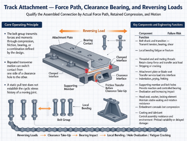
The mechanical interfaces determine whether the attachment preserves its intended load path. Material evidence must describe the finished components, and geometry evidence must describe the assembled contact. I identify both before deciding whether a fracture is caused by the bolt itself or by the members that repeatedly bend it.
| Component | Material Spec | Function | Failure Risk if Compromised |
|---|---|---|---|
| Bolt shank and transition | Verify alloy, finished properties, shank dimensions, and transition geometry. | Transmits approved tension, bearing, and shear loads. | Localized bending fatigue or fracture at a section change. |
| Threaded end and mating threads | Verify strength, tolerance, usable engagement, and damage condition. | Retains clamp force and transfers axial load. | StripPing or cracking at an overloaded engaged thread. |
| Attachment plate or blade seat | Verify material, thickness, flatness, and contact hardness. | Transfers service load into the compressed interface. | Local indentation, prying, or fretting. |
| Supporting member and bolt holes | Verify material, hole geometry, clearance, and repair condition. | Provides reaction and controlled bearing contact. | Hole ovalization and increasing impact motion. |
| Head seat, washer, and locking element | Verify bearing geometry, hardness, and locking behavior. | Maintains stable seating and approved resistance to rotation. | Embedment or restraint that conceals lost compression. |
| Coating and assembly lubricant | Verify finished condition, friction behavior, and process route. | Controls assembly resistance and environmental exposure. | Preload variability or delayed material damage. |
Verify all parameters against current test reports and applicable standards before use in specifications.
I do not describe a square neck, flange, or serrated face as an automatic fatigue solution. Its function depends on fit, bearing support, and the mating material. A feature that restrains rotation may still allow the member to settle. Head-seat damage and hole wear must be inspected separately from the locking device.
Repairs also change the component system. Welding near an attachment, enlarging a hole, or replacing a worn plate can modify stiffness and load introduction. The replacement bolt is then operating in a changed assembly. A repair drawing and its validation should define which original assumptions remain applicable.
I qualify duty using the assembled load history. The test must reproduce the damaging direction and sequence, including reversals and eccentricity where relevant. A force measurement at the machine actuator is not necessarily the force at the bolt group; I relate the two using geometry, measured reactions, and a checked structural model. Test limits cannot be invented from a nominal machine category.
| Parameter | Standard | Test Method | Acceptable Range | Implication if Out of Range |
|---|---|---|---|---|
| Applied force and moment history | Not supplied; verify the approved method. | Measure representative operating reactions and reproduce their sequence on the joint. | Verify the approved service envelope and qualification report. | A test may omit the critical load case. |
| Initial and retained clamp force | Not supplied; verify the approved method. | Measure preload before loading and after defined operating blocks. | Verify against current reports and joint analysis. | Increasing separation or transverse motion. |
| Relative member slip | Not supplied; verify the approved method. | Monitor displacement across the actual contact interface. | Verify design-permitted movement and measurement uncertainty. | Load transfers unexpectedly into shank bearing. |
| Cyclic bolt strain and local bending | Not supplied; verify the approved method. | Instrument representative locations without materially changing stiffness. | Verify approved analysis and correlated test response. | Damaging stress range is underestimated. |
| Hole wear and crack indication | Not supplied; verify the approved method. | Inspect geometry and apply a qualified crack-detection procedure at controlled interruptions. | Verify drawing limits and the approved inspection method. | Progressive wear or cracking escapes a survival-only test. |
Verify all parameters against current test reports and applicable standards before use in specifications.
A test report must retain interruptions, fixture repairs, and out-of-envelope events. If the attachment is retightened during a fatigue trial, the event changes the history and must not disappear from the result. I define whether such intervention is part of the intended service procedure or evidence that the original assembly condition was not maintained.
Protection begins by keeping the actual force path within the design assumptions. For a slip-resistant attachment, retained compression and interface friction must resist the relevant transverse action. For a bearing attachment, hole clearance, bearing area, and bolt location must support the permitted movement without excessive local deformation. A test that measures only applied load cannot distinguish these mechanisms. I monitor both load and motion so that survival is interpreted in the correct structural state.
Impact deserves a separate assessment from a slowly applied force. Contact compliance, clearance take-up, and the stiffness of the surrounding structure affect the local response. The load direction can also change as the member rocks. I establish representative impact conditions from operating evidence rather than applying an arbitrary multiplier to a catalog strength. A fixture that is more rigid than the production support can alter the response and make a component appear more stable than it is in service.
Fatigue depends on the local stress history and the condition of the initiating surface. Thread roots, head transitions, damaged shanks, and worn bearing locations can concentrate cyclic stress. Mean tension from assembly and fluctuating service tension interact, but neither a strength marking nor a static failure load establishes the fatigue response of the assembled joint. I correlate calculated force distribution with measured movement or strain before using that model to identify the critical fastener.
The torque-to-preload gap enters this problem at the starting state. Different coating, lubricant, washer condition, or Nut resistance can make the same tool setting establish different compression. If one attachment begins with less compression, it can slip earlier and accumulate more bending cycles than its neighbors. I qualify the assembly friction condition and its scatter before running the duty test, then monitor retained force afterward. This connects the installation process to the fatigue mechanism rather than treating them as unrelated checks.
Thread engagement must be assessed where the cyclic force is reacted. A tapped member that is damaged or too weak can progressively deform at the engaged flanks. An incomplete thread near the entry may not provide the assumed support. I identify usable engagement after chamfers, runout, and assembly clearance are accounted for. The analysis compares internal stripping, external-thread damage, and bolt failure using the actual materials. A longer nominal screw is not necessarily a stronger connection if its extra length only approaches the bottom of a blind hole.
The location of a shear plane matters when motion brings the bolt into bearing. A plane through the threaded region has different effective geometry and local stress concentration from one through the full shank. However, moving the thread out of that plane does not remove hole wear, eccentricity, or joint bending. I examine the assembled grip, head seating, and permitted contact positions together. Where the model leaves uncertainty, a representative assembly test must reveal the failure location and contact evolution.
Loss of compression need not be caused by nut rotation. Local indentation, wear debris, contact settling, and temperature-dependent member response can shorten the compressed stack. A locking device can restrain rotation while that loss continues. For this reason I evaluate locking behavior and residual compression separately. The duty test should establish whether the device retains its intended function after the same contamination, movement, and temperature sequence that the joint experiences.
Surface treatment creates another coupled protection problem. Corrosion resistance helps preserve sections and contact condition, but treatment processes may introduce hydrogen into susceptible material. Sustained assembly tension can then support delayed cracking. I require process identity, finished hardness evidence, applicable relief records, and approved mechanical verification rather than assuming a corrosion report establishes freedom from delayed fracture. No treatment schedule is specified without verified data.
When a fracture occurs, I distinguish fatigue, overload, delayed brittle damage, and mixed mechanisms using the load history and preserved surfaces. A corroded fatigue origin and a process-related embrittlement concern can coexist. Replacing the part with a higher-strength bolt changes the material and assembly assumptions and requires renewed validation. The protective logic is therefore a controlled evidence chain from finished component to installation state to duty response, not a single claim that stronger material survives harder service.
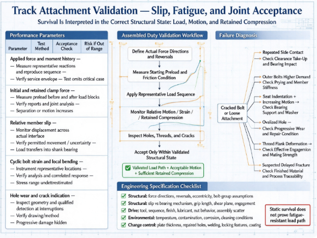
I examine the entire bolt group after a failure because the broken location may be the first symptom of load redistribution elsewhere. Witness marks, debris, hole shape, head seating, and retained preload provide evidence that a fracture photograph alone cannot supply. Mechanism-specific findings lead to the following distinct corrective paths.
Reversing-load bending fatigue follows when a plate repeatedly traverses clearance and bears against opposite sides of a bolt. The consequence is a stress concentration at the loaded section and progressive cracking. Prevention requires checking the intended slip condition, controlling fit and retained compression, and validating the reversal sequence on representative members.
Prying-related tensile fatigue follows when a flexible attachment bends around its contact region and adds tension to the outer bolts. The consequence is unequal bolt-group demand despite equal installation settings. Prevention requires analysis of contact position and member stiffness, followed by assembled measurements that confirm which locations carry the changing load.
Bearing-seat collapse follows when local pressure exceeds the support provided by the head seat, washer, or member surface. Compression decreases as the seat indents, and transverse movement then increases. Prevention requires verified bearing geometry and material response, plus inspection after representative load blocks rather than only immediately after installation.
Progressive hole ovalization follows when repeated bearing impact deforms the hole wall. The growing clearance raises movement and can accelerate bending damage. Prevention includes dimensional assessment of worn and repaired holes and qualification of the approved repair condition. A new bolt alone does not restore the original joint geometry.
Engaged-thread failure follows when the mating member cannot transmit the cyclic and assembly loads through its usable thread flanks. The consequence can be partial loosening followed by stripping. Prevention requires effective-engagement verification, material-capacity comparison, and controlled rejection of damaged tapped members.
Delayed fracture after apparently successful assembly can involve susceptible finished material, hydrogen exposure, and sustained tension. Prevention requires separate coating-process evidence and delayed-fracture evaluation. A passing duty specimen does not by itself establish the process capability of every manufacturing lot.
The specification must identify the assembled service state before naming the required evidence. I organize it under structural, drive, environmental, and safety categories so that changes to equipment duty or repair practice can be reviewed against a defined boundary.
Structural: define the actual force directions, reversals, eccentric moments, attachment geometry, and allowed load-sharing assumptions for the bolt group.
Structural: identify whether the connection is intended to resist slip or transfer load through bearing, and define the permitted movement from validated evidence.
Structural: verify grip length, shear-plane location, hole clearance, usable thread engagement, member stiffness, and bearing support against current drawings and reports.
Structural: define retained preload, crack inspection, hole wear, and fatigue acceptance through the approved assembled test program.
Drive specifications: control tool configuration, tightening sequence, finish, lubricant, nut behavior, and assembly scatter associated with the qualified starting state.
Environmental: reproduce temperature, abrasive contamination, corrosion exposure, and cleaning conditions that can alter friction or contact condition.
Safety standards: confirm project-required standards through the approval process; no standard designation or certified performance is supplied here.
Change control: require review for altered plate thickness, repaired holes, welding near the joint, replacement locking features, or a changed material or coating route.
The acceptance record must state which interventions are allowed during a trial and which invalidate it. Retightening, fixture replacement, and specimen substitution are material events. I retain measurements before each intervention so that recovery does not erase the evidence needed to explain why compression or alignment was lost.
Ningbo yi teng construction machinery CO,LTD is described in the supplied information as producing Blade Bolts, Track plate bolts, Crusher Bolts, and related machinery components. The bolts product page should distinguish these configurations and their engineering evidence instead of presenting a shared product category as a common duty rating.
I evaluate whether a manufacturer can reproduce attachment geometry, retain individual assembly traces, and conduct or coordinate assembled cyclic tests. Mechanical characterization must be linked to the finished condition and lot identity. A laboratory should explain the difference between a fastener tensile result and a complete connection fatigue result.
Failure-analysis capability includes preserving fractured parts, documenting interfaces, examining thread and bearing damage, and testing a proposed correction under the same duty. I also expect a clear boundary between approved original geometry and repaired or modified equipment. No current certification is established by the supplied technical-standards field; verify any certification required for specification independently.
Yes, a static test does not establish the cyclic stress history of a moving joint.
Clearance take-up, bearing impact, and bending can create repeated local demand absent from a static test. I validate the assembled reversal sequence and monitor relative movement. Fatigue acceptance must be based on the approved duty and current evidence.
No, a locking nut can resist rotation while compression falls through embedment or member deformation.
I measure retained preload separately from locking resistance. Inspecting the nut position cannot establish the compression remaining in the stack. The test must include the contact settling and temperature conditions relevant to service.
That choice requires explicit assessment of the designed bearing and shear load path.
Threaded and unthreaded sections have different effective geometry and local stress concentration. I check the actual grip and permitted contact positions rather than making a universal assumption. Verify the accepted configuration against current assembly analysis and test reports.
Only when the worn or repaired geometry has been assessed and validated.
Ovalization changes clearance, bearing contact, and motion. A replacement fastener restores neither the original member stiffness nor the original hole shape. The repair condition needs its own drawing and acceptance evidence.
Record the joint state before intervention and assess whether the interruption changes the qualification history.
Retightening or changing the fixture can remove the condition that caused the failure trend. I distinguish an approved service intervention from an unplanned rescue of the specimen. Acceptance must disclose the actual sequence rather than reporting uninterrupted survival.
Share your project parameters for a technical review.
Personne à contacter : Mme Wu
Téléphone :0086-13958324455
Service client : +86-0574 88065928
Courriel : Sales@zjbzj.com
Télécopie : +0086-0574 88065656

site officiel
Copyright @ Ningbo yi teng construction Machinery CO, LTD, principalement engagé dans la série de boulons de lame, les boulons hexagonaux et les dents de godet. Bienvenue à vous renseigner !
Plan du siteCe site Web utilise des cookies pour vous garantir la meilleure expérience sur notre site Web.
 English
 Español
 Portugues
 Pусский
 Deutsch
 日本語
 한국어
 العربية
 हिन्दी



 WhatsApp
 Téléphone
Commentaire
(0)